Multiplex image alignment

Register images from multiplexed imaging round

Data Organization

The images from each round are expected to be in 2D and as an image sequence. All the images need to be in the same folder and they have to follow a naming convention:

XXXX_layer1_markername.tif

The XXXX can be anything you want. markername should be name of the marker or label you use for that image.

For example, if a multiplexing round is called "Layer" and each round has a number, then images from first round should have Layer 1 or layer1. So, if sample id is sample1, its the first round and marker is Hu, then image name should me `sample1_layer1_Hu.tif`. The names can have a mix of upper and lowercase.

For example, we're using data from Chen et al. 2023, specifically myenteric wholemount from the descending colon. Multiple ganglia were imaged, so the naming convention we've used is:

H2202Desc_Layernumber_Ganglia1_marker.tif

The layer number and marker change with each file.

For this dataset, we have:

  • 14 different markers

  • 6 different rounds of staining

  • Every round has pan-neuronal marker Hu as a reference marker.

So, if the images were in E:/Multiplex, then the images will be organized like this:

├──E:/Multiplex
│   ├── H2202Desc_Layer 1_Ganglia1_Hu.tif
│   ├── H2202Desc_Layer1_Ganglia1_5HT.tif
│   ├── H2202Desc_Layer1_Ganglia1_ChAT.tif
│   ├── H2202Desc_Layer1_Ganglia1_NOS.tif
│   ├── H2202Desc_Layer2_Ganglia1_CGRP.tif
│   ├── H2202Desc_Layer2_Ganglia1_Enk.tif
│   ├── H2202Desc_Layer2_Ganglia1_Hu.tif
│   ├── H2202Desc_Layer2_Ganglia1_SP.tif
│   ├── H2202Desc_Layer3_Ganglia1_Hu.tif
│   ├── H2202Desc_Layer3_Ganglia1_Somat.tif
│   ├── H2202Desc_Layer3_Ganglia1_VAChT.tif
│   ├── H2202Desc_Layer4_Ganglia1_Hu.tif
│   ├── H2202Desc_Layer4_Ganglia1_NPY.tif
│   ├── H2202Desc_Layer5_Ganglia1_Calb.tif
│   ├── H2202Desc_Layer5_Ganglia1_Calret.tif
│   ├── H2202Desc_Layer5_Ganglia1_Hu.tif
│   ├── H2202Desc_Layer5_Ganglia1_NF.tif
│   ├── H2202Desc_Layer6_Ganglia1_Hu.tif
│   ├── H2202Desc_Layer6_Ganglia1_VIP.tif
How the analysis works (Click to expand)

GAT uses Scale Invariant Feature Transform (SIFT) as the primary method of identifying landmarks in the images. SIFT is a popular algorithm as its not really affected by image scale, rotation and quite robust to image noise and illumination.

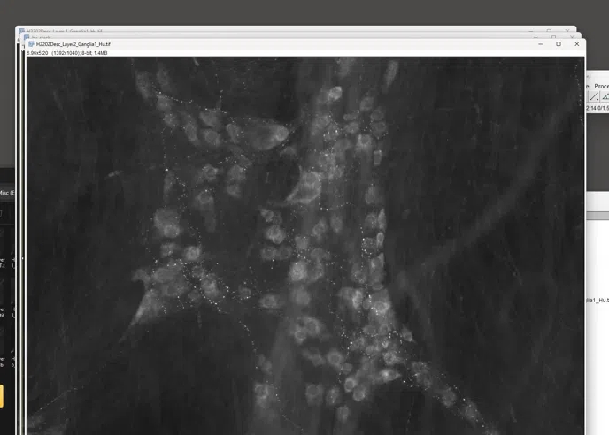
In the data we used above, Hu is the reference image across every multiplexing round. Example of reference image showing the misalignment across rounds.

### Image Alignment Process
The alignment process begins by identifying key 'landmarks' in the reference Hu channel from the first round of multiplexing. For each subsequent round, GAT:

1. Opens the Hu image.
2. Extracts key landmarks.
3. Compares these landmarks to those from the first round.
4. Calculates a transformation matrix.
5. Maps the current round onto the first round, using the Hu channel as the reference.

The landmarks extracted in each round are saved as an ROI Manager file in the Results folder.

Example of key landmarks detected on an image:

Algorithms used

For efficient alignment of images in our multiplexing workflow, initially, we employ the Extract SIFT Correspondences plugin available in Fiji. If SIFT does not yield a sufficient number of landmarks, we try Extract MOPS Correspondences plugin. MOPS, or Maximally Stable Extremal Regions, are another form of feature descriptors.

Should both SIFT and MOPS prove inadequate, our last option is to use the Extract Block Matching Correspondences plugin. Although not as advanced as SIFT or MOPS, this approach can still be effective by matching blocks of pixels between images to find corresponding points.

Note: The quality of your results from GAT alignment can be impacted by the choice of reference marker, the clarity and quality of the images, and the number of landmarks used. You could try adjusting settings using Finetune_parameters checkbox

Pleas note that we've only tested this on images of size 1500 x 1500 pixels in size. If you're having trouble running this on other image sizes, do get in touch.

Now we'll go through the analysis pipeline. The data for this tutorial can be downloaded from Zenodo.

Note:

While the example provided uses Hu as the reference image for alignment purposes, you may select any marker that effectively labels the majority of structures of interest within your samples. For instance, DAPI is commonly used as a reference marker in many fluorescent imaging protocols, due to its strong and consistent labelling of all cell nuclei.

Successful alignment depends heavily on the the quality of the reference marker labeling

Analysis Steps

1. The images from various rounds are stored with the specified naming convention

2. Go to GAT->Multiplex->Multiplex Registration

3. Select the directory. Enter the name of the reference marker present across all rounds, in this case "Hu". Enter the number of rounds of multiplexing. Also enter the name that distinguishes each round of multiplexing. In this case, we've entered "Layer".

You can also choose a different folder to save your data or finetune your alignment parameters by ticking the boxes below.

Click Ok when you're done.

4. Once you click Ok, the images from each round will open up and the alignment process begins. Information will be printed out to the Log window. An ROI Manager file will also appear which contains the landmarks for alignment.

5. Once you're done, you'll be left with your aligned image!

6. The Results will be saved in the save_directory selected before.

7. The Results folder will contain the aligned image stack. It will also contain a stack of reference channels from each round, in this case Hu with a corresponding ROI manager file. This ROI Manager file contains landmarks used to align Hu channel from each round to the reference image, which is the image from the first round/layer of multiplexing

References

  1. Lowe, D. G. (2004). Distinctive Image Features from Scale-Invariant Keypoints. International Journal of Computer Vision, 60(2), 91–110. doi:10.1023/b:visi.0000029664.99615.94

  2. Brown, M., Szeliski, R., & Winder, S. (n.d.). Multi-Image Matching Using Multi-Scale Oriented Patches. In 2005 IEEE Computer Society Conference on Computer Vision and Pattern Recognition (CVPR’05). IEEE. doi:10.1109/cvpr.2005.235

  3. Fischler, M. A., & Bolles, R. C. (1981). Random sample consensus. Communications of the ACM, 24(6), 381–395. doi:10.1145/358669.358692

Made with Scribe

Last updated